The Spin Valve
 At Leeds we have built a variety of different spin-valve structures as part of a giant-magnetoresistance (GMR) sensor project. A spin valve is in general a sample consisting of a GMR trilayer - two magnetic layers separated by a non-magnetic spacer. One of the two magnetic layers is very magnetically soft - meaning it is very sensitive to small fields. The other is made magnetically 'hard' by various schemes - meaning it is insensitive to fields of moderate size. As the soft 'free' layer moves about due to applied fields, the resistance of the whole structure will vary.
In Leeds, our magnetic layers are usually made from permalloy (NiFe) with a thin covering of Co, and are separated by a Cu spacer. One magnetic layer is pinned or exchange biased by an antiferromagnetic material - we have been using FeMn and IrMn, as they are easily prepared.
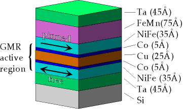
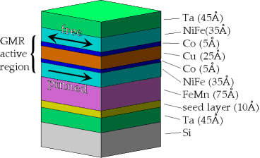
The figure below illustrates the most common form of spin-valve design - referred to as a top spin valve, since the biased layer is at the top. It is the simplest to fabricate in our sputtering system. The thin Co inserts serve a dual purpose - the Co/Cu interface gives a larger GMR ratio, and also the Co acts as a diffusion barrier for the permalloy and Cu, which are miscible (Co/Cu is immiscible). As in all the diagrams shown on this page, layer thicknesses are typical values for such a sample.
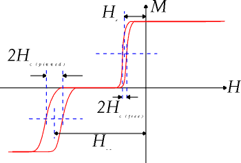
This is a schematic of the magnetisation loop of such a sample - it consists of the hysteresis loops of the two magnetic layers added together. The pinned layer switches far from zero field due to the exchange bias. The free layer should ideally switch about zero field, in practice there is a small offset due to coupling to the pinned layer. In the flat region where the net magnetisation is zero the resistance of the sample is high, since the layer moments are antiparallel. The steep slope of the free layer is used to sense fields.
This design is called a bottom spin valve - the biased layer is now at the bottom. This presents some growth problems as the biasing FeMn layer does not grow on top of a magnetically saturated film - so its magnetic structure is random.
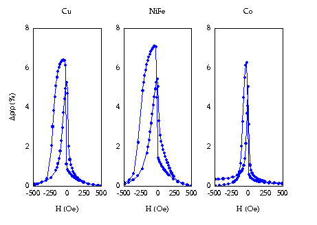
 The graphs show the results for as-deposited films on top of different seed layers. In the case of permalloy (NiFe) there is appreciable exchange biasing already - but not in the case of a Co seed layer. Therefore we can see that a magnetic seed layer is not necessary. The use of Cu shows that the requirement is to have a seed layer with an fcc crystal lattice, to nucleate the right phase of FeMn growth. All of these results can be improved upon field annealing to make a more useful structure with an AF plateau in the MR response. It seems that the quality of the final structure is roughly in proportion to the as-deposited film however.
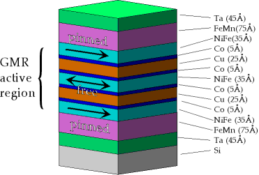
The following design is called a symmetric spin valve - it has three magnetic layers, and two Cu spacer layers, and therefore twice as many GMR active Co/Cu interfaces as the previous two designs. The topmost and bottommost magnetic layers are pinned by FeMn. It is effectively a top and a bottom spin valve stuck together. This means we face the usual problems in pinning a layer from below when making this type of structure.
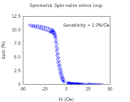
 This graph shows the low-field response of a symmetric spin valve which has been field-annealed to ensure both top and bottom layers are pinned. This field was also applied at right angles to the original as-grown pinning direction. This means that when we apply our field to be sensed along the new pinning direction it is at right angles to the easy axis of the free layer, which is also defined by the growth field direction. The free layer is now being swept in a hard axis, and shows reduced hysteresis, and a more linear response. The ressitance of the sample changes by approximately 10% in 10 Oe, leading to an raw sensitivity of 10%/Oe.
The last type of spin valve has the pinned layer replaced by an AF coupled trilayer of Co/Ru/Co - sometimes referred to as a synthetic antiferromagnet. This AF coupling is extremely strong. When the applied field tries top reverse the top Co layer moment (next to the FeMn), the torque it exerts is counteracted exactly by the torque from the Co layer it is coupled to. The field has to break down the AF coupling to reverse the pinned layer.
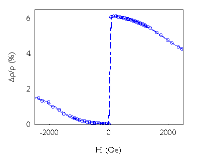
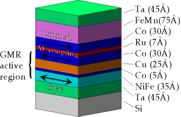 This graph shows the GMR response of such a spin valve. The free layer will switch in a very small field, as usual for a permalloy layer. Meanwhile the pinned layer is very robust against even quite large fields - it barely moves in fields of up to 1000 Oe. As a result such structures can be used up to higher operating temperatures, as there is still substantial pinning at over 100 degrees C. This can improved further by the use of pinning materials which can be used up to higher temperatures than FeMn.